A Graph is a non-linear data structure just like a tree. A Graph is defined as a set of vertices also called nodes and edges also called arcs. The graph is a very important data structure to solve real-life problems like “What is the fastest way of going from Spain to the USA”. These real-life problems can be easily solved by the Graph.
In this tutorial, We will know the basic terminology of graph data structure, representation of graphs and then we will deep dive into the implementation of Graph and traversal algorithms using JavaScript.
Contents [hide]
Definition
A graph G is represented as G = ( V, E ), where V is a set of nodes or vertices and E is a collection of pairs of vertices, called edges.
1. Graph Terminology
-
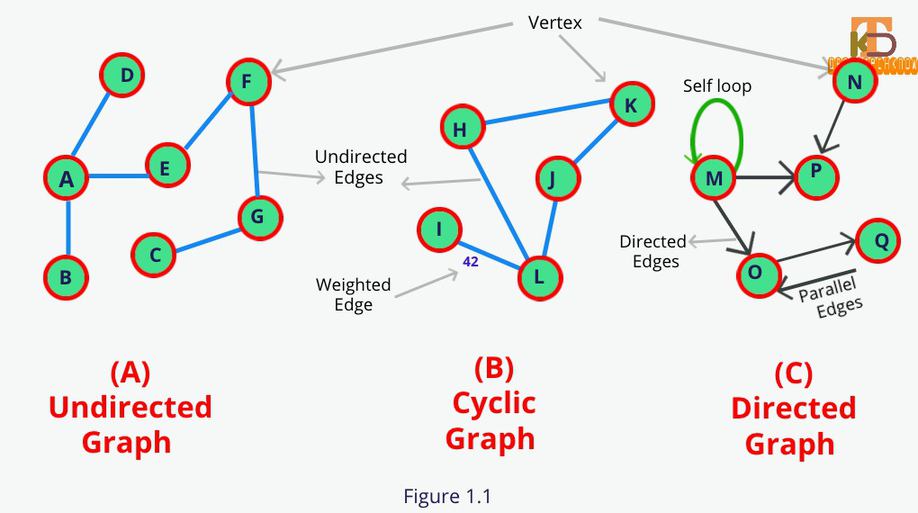
Vertex (V)or node is a data element of a graph. A vertex is denoted byVand represented by the circle.
-
An Edge (E)is a connection between the Vertices. It is denoted by E and represented by a straight line.Edges are three types directed edge, undirected edge, and weighted edge.
-
Directed Edge: Unidirectional edge between the vertices is called directed edges. If a directed edge exists in between A->B then there is a path from A to B but not From B to A.
-
Undirected Edge: Bidirectional Edge between the vertices is called undirected edges. If an undirected edge exists in between A-B then there is a path from A to B and B to A.
-
Weighted Edge: An edge that contains the weight or cost on it.
-
-
Directed Graph or Digraph is a type of graph that has only the directed edges.
-
Undirected Graph or Graph is a type of graph that has only the undirected edges.
-
A Degree is a count of edges that are connected to vertex V. Degree can of two types
-
In-degree is a count of incoming edges in the directed Graph that are connected to Vertex V. Like in fig 1.1 indegree of vertex Ois 2 and outdegree is 1.
-
Out-degree is a count of outgoing edges in the directed Graph that are connected to Vertex V.
-
-
A self-loop is an edge that connects a vertex to itself.
-
Parallel edges are those edges that are connected through the same pair of vertexes.
-
The path is defined as the sequence of vertices that are traveled to reach some destination node.
-
A Cycle is a path where the first and the last vertex is the same. PathHKJLHis a cycle.
-
Connected Graph(A) is one where there exists some path between every two vertices. There is no isolated node in the connected graph.
-
Non-connected Graph is a graph that contains two or more components. If we add graphsAandBthen the composite graph is called a non-connected graph.
-
A simple Graph is a graph with no self-loop and no parallel edges.A and Bboth are simple graphs.
-
Strongly-Connected Graph is one where there exists a path from each vertex to every other vertex.
-
Complete Graph is one where each node is connected to every other node in the graph.
-
Directed Acyclic Graph is a directed graph with no cycle.
2. Graph Representation
There are mainly two ways to represent the graph data structure.
-
Adjacency list
-
Adjacency Matrix
2.1 Adjacency list
In this representation, we have a list of all the nodes and for each node, we have a list of nodes for which the node has an edge. We can use array, map, or object for implementation of the graph using the Adjacency list but here we will use the Object for storing graph data.
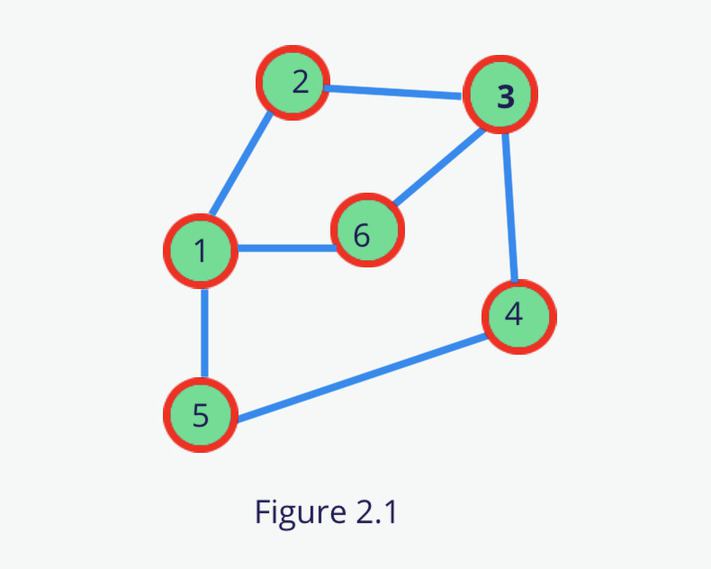
So let’s implement the below graph using the Adjacency List.
-
Save all the nodes as an object key.
-
For each node, prepare a list of adjacent nodes.
2.1.1 Implementation of Graph using Adjacency List
2.2 Adjacency Matrix
A 2D matrix of VxV is used to represent the graph where V corresponds to a vertex of the graph. In this matrix, we store if there exists an edge between the two vertexes else we will fill it to 0.
If the element a[i][j] is 1 then there should be an edge between the vertex i and vertex j.
Let’s implement the same graph(fig 2.1) using the Adjacency Matrix.
2.2.1 Implementation of Graph using Adjacency Matrix
3. Graph Traversal
3.1.1 Breadth-First Search
BFS is a graph traversal technique. It is similar to Level-Order traversal in the tree. In fact, Level order traversal got inspired from BFS. It visits all the vertexes of the graph level by level. Initially, BFS starts with given vertex and visit all other vertexes level by level.
3.1.2 Implementation of BFS
To implement the BFS, we used the queue data structure to store the adjacent vertexes data. We are first creating the same graph which is shown in fig 2.1 and traversing it.
3.2.1 Depth First Search
DFS is working in the same manner as the preorder traversal works in the tree. It recursively visiting each vertexas far as possible along each branch.
3.2.2 Implementation of DFS
Like preorder traversal, DFS uses the same data structure stack to store the vertexes information. We are again using the same graph which is in fig 2.1.